

LED Current-Limiting Resistors: The 2-Minute Math
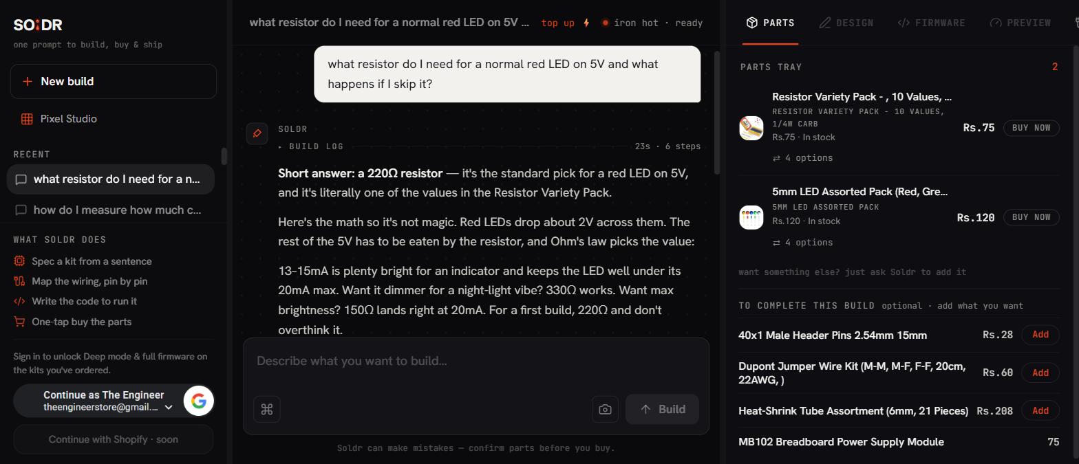
The resistor for an LED is calculated in one line: R = (supply voltage − LED forward voltage) ÷ desired current. For a red 5mm LED on a 5V Arduino pin at 10mA, that is (5 − 2) ÷ 0.010 = 300Ω, so you grab the nearest standard value, 330Ω, and you are done. The resistor exists because an LED is not like a bulb: it does not regulate its own current. Below its forward voltage it passes almost nothing; a whisker above, it passes as much current as the supply can shove through it, heats up, and dies in seconds. The resistor takes up the leftover voltage and, by Ohm's law, fixes the current at a value the LED enjoys. Two minutes of arithmetic, a lifetime of unburned LEDs.
Why an LED cannot be trusted alone
An LED is a diode, and a diode's current-voltage curve is a cliff, not a slope. A red LED conducts essentially nothing at 1.5V, a pleasant glow's worth around 1.9V, and a destructive flood at 2.2V. No supply holds its voltage that precisely, and the LED's own cliff shifts as it warms up, in the wrong direction: hotter means more current at the same voltage, which means hotter still. Engineers call this thermal runaway. Connect an LED straight across a stiff 5V supply and this loop completes in moments; the flash of brightness before the dark is the chip bond wire failing.
The resistor breaks the loop. Being a plain linear device, it drops voltage in exact proportion to current. Now if current tries to rise, the resistor's drop rises too, which leaves less voltage for the LED, which pushes the current back down. The pair settles at a stable operating point that you choose with the resistor value.
The three numbers you plug in
Supply voltage (Vs): whatever feeds the circuit, 5V from an Arduino Uno R3 pin, 3.3V from an ESP32, 12V from an adapter.
Forward voltage (Vf): the LED's own drop, set by its chemistry, which is to say its colour. Working numbers: red about 2.0V, yellow 2.0V, green (standard) 2.1V, blue and white about 3.0 to 3.2V. Datasheets refine this, but the working numbers land you close enough.
Current (If): your choice. Most 5mm LEDs are rated for 20mA maximum, but modern LEDs are bright; 5 to 10mA gives excellent indicator brightness and long life. Choosing 10mA rather than 20 is not caution, it is taste; many finished products run indicators at 2mA.
Then R = (Vs − Vf) ÷ If, and round up to the next standard value in the resistor variety pack. Rounding up nudges current slightly lower, the safe direction.
Worked example, twice over
Red LED, 5V pin, 10mA: R = (5 − 2.0) ÷ 0.010 = 300Ω → use 330Ω. Actual current: 3 ÷ 330 ≈ 9mA. On a 400-point breadboard: pin 9 through the 330Ω to the LED anode (the long leg), cathode to ground with a Dupont jumper wire. The resistor works on either side of the LED, before or after; the loop current is the same everywhere in a series path.
Blue LED, 3.3V board, 8mA: R = (3.3 − 3.0) ÷ 0.008 ≈ 37Ω → use 39Ω or 47Ω. Notice how little headroom is left: only 0.3V above the forward voltage. On 3.3V systems, blue and white LEDs sit near the cliff edge, so real brightness varies noticeably between individual LEDs and with temperature. It works, but this is why designers prefer a higher rail or a proper LED driver when blue or white output must be consistent.
Power check, occasionally worth doing: the resistor dissipates I²R. At 9mA through 330Ω that is 0.027W, nothing to a quarter-watt resistor. Only on higher-voltage supplies does this need thought: a 12V supply and a 2V LED at 20mA puts half a watt into a 500Ω resistor, which needs a 1W part or the load split across two.
Where this bites you
The signature beginner move: connecting an LED with no resistor "just to try it", seeing it light, and concluding the resistor is optional. Sometimes the LED dies at once and teaches the lesson cheaply. The misleading case is when it survives: an Arduino pin's internal resistance and current limits partially protect the LED, so it glows away merrily while both pin and LED run outside their ratings, aging fast. It worked, but only in the sense that skipping a helmet works until it does not. The pin can be permanently weakened even when the LED lives.
Second trap: one calculated value reused everywhere. The 330Ω that suits a red LED on 5V starves a blue LED on 3.3V into dimness and overdrives nothing on 12V. The formula takes 30 seconds; run it per colour, per rail.
Third: wiring the LED backwards. No harm at these voltages, just darkness, since a reversed diode blocks. Long leg is the anode and goes toward positive; the flat spot on the package rim marks the cathode. If an LED refuses to light, reverse it before redesigning anything.
FAQ
Does it matter which side of the LED the resistor goes?
Electrically, no. In a series loop the same current flows through every element regardless of order, so anode side or cathode side limits identically. Pick whichever makes the breadboard tidier.
Can I skip the resistor if I dim the LED with PWM?
No. PWM switches between fully on and fully off, and during every on-slice the LED sees the full supply with nothing limiting current. Average current being low does not save it; the peaks do the damage. PWM controls brightness, the resistor controls current, and you need both.
Why did my LED get dimmer over months of use?
Sustained overcurrent degrades the LED die and its phosphor (in white LEDs), permanently reducing output. An LED run at or beyond its maximum rating can lose noticeable brightness within months. Run indicators at a third of maximum and they outlast the project.
Compoden's AI build assistant Soldr runs this exact calculation automatically when it wires LEDs into your project, one resistor per LED, matched to your board's voltage.
- Resistor Variety Pack — 100 Pcs, 10 Values, 1/4W — includes 330Ω and every other common value you'll need
- 5mm LED Assorted Pack — Multi-Color — red, green, blue, yellow, white to practise the formula on each colour
- LED Variety Pack (50 pcs) — 3mm & 5mm Mixed — more LEDs, more colours, more experiments
- 100x 10Ω 1/4W Resistors — when you need a specific low value in bulk
- MB102 Breadboard with Power Supply — prototype the circuit cleanly with switchable 3.3V/5V rails